 |
| |
|
Multiplane Anchorage MA |
|
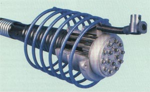
The two-part
multiplane anchorage is primarily used for longitudinal tendons in beams and
bridges .
The wedge plate with
the conical anchor body and usually three load transfer planes introduces the
prestressing force continuouslyinto the member with minimal front area .
The separation of
anchor body and wedge plate makes it possible to insert the strand after casting
the concrete .
The wedge plate self
centers on the anchor body providing consistent assembly and installation as
well as trouble free stressing . |
|
|
|
stressing
anchorage |
dead end anchorage |
coupling |
ultimate load
(kN) |
|
accessible |
not accessible |
from |
to |
| |
|
|
|
1.302 |
17.019 |
|
|
|
pocket
former for each anchorage system on request
|
|
|
|
Technical Data |
|
type
0.5¹¹ |
ultimate load
Ǿ 12.9 mm
(186kN per strand) |
type
0.6¹¹
|
ultimate load
Ǿ 15.7 mm
(279kN per strand) |
A |
B |
C1 |
C2 |
D |
|
KN |
KN |
mm |
mm |
mm |
mm |
mm |
|
5907 |
1.302 |
6905 |
1.395 |
117 |
150 |
36 |
90 |
190 |
|
5909 |
1.674 |
6907 |
1.953 |
130 |
170 |
40 |
100 |
200 |
|
5912 |
2.232 |
6909 |
2.511 |
140 |
180 |
43 |
125 |
300 |
|
5915 |
2.790 |
6912 |
3.348 |
160 |
220 |
44 |
180 |
350 |
|
5919 |
3.534 |
6915 |
4.185 |
180 |
250 |
51 |
200 |
400 |
|
5927 |
5.022 |
6919 |
5.301 |
200 |
280 |
55 |
220 |
450 |
|
5932 |
5.952 |
6922 |
6.138 |
220 |
300 |
66 |
220 |
550 |
|
5937 |
6.882 |
6927 |
7.533 |
240 |
315 |
75 |
240 |
600 |
|
5955 |
10.230 |
6937 |
10.323 |
270 |
390 |
90 |
350 |
600 |
|
- |
- |
6961 |
17.0.19 |
340 |
490 |
143 |
405 |
800 |
|
|
| |
|
Details Of The Anchorage
Zone
|
|
Ǿ 12.9/15.7mm,
ultimate load 186/265 KN |
|
type
0.5¹¹ |
type
0.6¹¹ |
distances of the
anchorage |
additional reinforcement |
|
helix |
|
centre
distances |
edge
distances |
E |
F |
n |
e |
|
mm |
mm |
mm |
mm |
|
mm |
|
5907 |
6805 |
220 |
130 |
190 |
220 |
5 |
12 |
|
5909 |
6807 |
260 |
150 |
200 |
290 |
5 |
14 |
|
5912 |
6809 |
310 |
175 |
240 |
330 |
6 |
14 |
|
5915 |
6812 |
350 |
195 |
280 |
300 |
6 |
14 |
|
5919 |
6815 |
390 |
215 |
320 |
340 |
6 |
16 |
|
5927 |
6819 |
440 |
240 |
360 |
390 |
7 |
16 |
|
5932 |
6822 |
470 |
255 |
380 |
420 |
7 |
16 |
|
5937 |
6827 |
530 |
285 |
430 |
480 |
7 |
16 |
|
- |
6837 |
620 |
340 |
540 |
550 |
7 |
20 |
|
- |
6861¹ |
800 |
420 |
680 |
705 |
8 |
25 |
|
|
|
¹ rectangular shape
² additional surface reinforcement in area G required alternate reinforcement
on request
|
| |
|
Ǿ 12.9/15.7mm,
ultimate load 186/265 KN |
|
type
0.6¹¹ |
distances of the
anchorage |
additional reinforcement |
|
helix |
|
centre
distances |
edge
distances |
E |
F |
n |
e |
|
mm |
mm |
mm |
mm |
|
mm |
|
6905 |
|
130 |
190 |
220 |
5 |
12 |
|
6907 |
|
150 |
200 |
290 |
5 |
14 |
|
6909 |
|
175 |
240 |
330 |
6 |
14 |
|
6912 |
|
195 |
280 |
300 |
6 |
14 |
|
6915 |
|
215 |
320 |
340 |
6 |
16 |
|
6919 |
|
240 |
360 |
390 |
7 |
16 |
|
6922 |
|
255 |
380 |
420 |
7 |
16 |
|
6927 |
|
285 |
430 |
480 |
7 |
16 |
|
6937 |
|
340 |
540 |
550 |
7 |
20 |
|
6961¹ |
|
420 |
680 |
705 |
8 |
25 |
|
|
|
¹ rectangular shape
² additional surface reinforcement in area G required
|
|
|
|
he values for the
anchorage are based on FIP concrete strength after 28 days of 25N/mm² (cube) or
21 N/mm² (cylinder)
possible to apply to other code systems or concrete strengths.(e.g. ASTM, BS,DIN
and concrete strengths of 35N/mm², 45
N/mm² )
Max. prestressing load 75% of ultimate load (GUTS) (short term overstressing to
80% is permissible) |
| |
|
Back |
| |
| |
| |